EPISODE IV: A NEW HOPE
Used by: Obi-Wan Kenobi


"This is the weapon of a Jedi Knight. Not as clumsy or random as a blaster. An elegant weapon for a more civilized time." - Obi-Wan Kenobi
Obi-Wan Kenobi remembered that more civilized time, before his colleagues fell and darkness enveloped the galaxy. The great Jedi met his own destiny wielding this lightsaber against his former pupil, Darth Vader.
The construction of this prop was much more complex than the other lightsabers of Episode IV: A New Hope.
First is the blade emitter which has yet to be identified. It could be some type of gas burner or a rosebud type torch tip used in sheet metal work. On the opposite end of the spectrum it could even be a piece for fire suppression equipment. An early theory was a sink drain for a vanity or bar likely made by a European manufacturer.
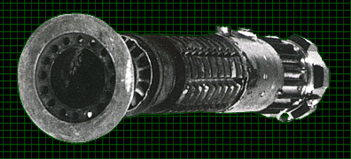
Next down the shaft of the saber is a large section of a WWI British rifle grenade, the No. 3 Mk. 1. (see below). Click here to see more detailed images of a similar grenade, a No. 20 Mk. 1, owned by Bob Poate. The U-shaped prongs were to clamp the grenade to the front of a rifle like the British Enfield No.1 Mk.III (the same rifle used for the Jawa Ion Gun). These prongs were soldered to the brass piece below, this bond was broken and the brass piece remained for the emitter pieces to attach to.
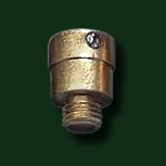
Brass Grenade Piece for the Emitter
(Note: These parts were also made in copper)
The long rod was obviously removed as was the safety pin and the brass locking sleeve it held in place. On a functional grenade removal of the safety pin and sleeve would release the windvane which would spin off while the grenade was in flight and arm it. The grenade appears to have not been painted at all for the prop. The shiny part of the saber neck below the emitter was kept naturally clean by the locking sleeve the rest of the brass appears highly oxidized and the heavy metal fragmentation body (grip section) appears darkened with age and probably even a bit rusty.
On the right side of the image immediately below is a detonator cap which would normally secure the interior parts of the grenade. The cap and any internal parts left were likely removed leaving the grenade hollow for a pipe or some inner core for the lightsaber parts to be assembled onto.

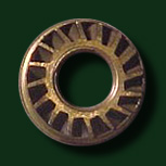
WWI British Rifle Grenade No.3 Mk.1 and top view of "ring" piece
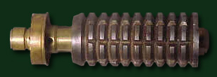
No. 3 Mk.1 with pieces removed and ready to be made into a saber
(Emitter connecting piece not pictured)
photos: Darryl Lynn - The Grenade Recognition Manual
A mounting clamp from a Graflex 3-cell flash unit, like that used for the Skywalker lightsaber, was used as the control box. Inserted into this clamp is a Light Emitting Diode display bubble type lens from a vintage calculator. These lenses are 2 inch long clear strips with a row of convex lenses referred to as "bubbles" to magnify the glowing red LED numbers. The lenses used on the lightsaber props had seven bubbles. Very few calculators have 7 bubble lenses so far only two models are known, the Exactra 19 and the Exactra 20. These were introduced by Texas Instruments in 1974 and are referred to as 6 digit displays (only six of the spaces are used for numbers, the leftmost is for modifiers like a negative sign).
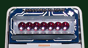
Texas Instruments Exactra 20 interior detail
Photo: Justin of World Famous Comics
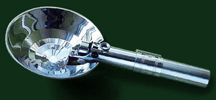
Graflex 3-Cell Flash Unit
On the side of the Graflex band are two metal buttons. These are transistors scavenged from some electronics component. The dark areas visible in the center of each button are printed manufacturers markings. Metal rings went around both transistors, but the ring around the upper button fell off (presumably during filming). The photo at top shows the ring missing, but photos taken during filming on location in Tunisia clearly show rings around both transistors.
Other details on the clamp are likely for assembly reasons not cosmetic. A set screw is located above the lever up close to the clamp bars. This screw apparently secures the clamp to the grenade body. Two metal wires are threaded through holes along the bottom of the clamp band and into the gear-like piece below. One is close to the side bars on the side opposite the lever and the other is located under the letter "A" in GRAFLEX. These wires may only have been added to stop the "gear" from rotating.
Below the clamp is a questionable part. It may be a 16 tooth gear from an industrial machine, possibly a lathe. The other main possibility that we have heard from well informed sources is that it's a custom-made heat sink, constructed from a tube and welded fins. If it was a heat sink then it was likely custom made for a special electronics application and then scavenged by the prop makers. There are other possibilities as well unfortunately there may never be a definitive answer.
The final part of this prop, used as the lightsaber pommel, was a faucet knob made in England (where the part is called a handwheel). The assumed manufacturer of the original prop part is Armitage Shanks. The company currently produces a very similar model listed in their catalog as Millennia Traditional Handwheels (part #63714XXCP). Their packaging refers to them as Starlite Universal Chrome Handwheels. These modern handwheels are different than their vintage counterparts. Most notably they have a slight taper to the knob where the originals had none. They also have a plastic blue or red ring around the top, but this piece is easily removed. As well, the current versions are made of plastic and have been vacu-metalized where the originals were metal likely brass (nickel and/or chrome plated). There are many other subtle differences but this is the closest available match currently in production.
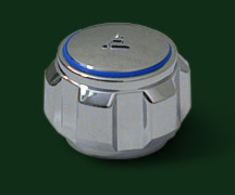
Armitage Shanks Millennia Traditional Handwheel (Modern Plastic Version)
A hole was drilled through one of the handwheel's protrusions through which a D-ring was added.
 |
|
|||||||||